The Coastal Mapping Program: Foundations 1807 - 1987
One of the missions of NOAA's National Geodetic Survey (NGS) is to survey the 95,000 miles of U.S. coastline, to provide an accurate, consistent, up-to-date national shoreline. The national shoreline provides the baseline data for making nautical charts and defining America's marine territorial limits, as well as the geographic reference needed to manage coastal resources, and for many other uses.
- Introduction
- Origin of the Program
- Aerial Photography
- Multi-Lens Cameras
- Color and Infra-red Photography
- C&GS-
Operated Planes - Conclusion
Imagine it is 1807. You are the captain of a ship sailing across the Atlantic Ocean, bringing goods to the bustling ports of the young United States. Using the latest navigational instruments, you are confident that you will make it to port successfully.
As your vessel approaches the harbor, you start to worry. You can see the wreck of a ship that appears to have grounded on a rocky shoal. You have the best available charts of the American coast, but it is likely that the captain of the grounded ship had the same charts. As you pass the wreck, you notice that your chart does not show a dangerous shoal in that location.
Current charts of the American coastline are not bad, but they could be much better. The last time you were in port, you heard talk about the U.S. Congress passing an act to survey the U.S. coasts. Perhaps something is going to be done to help mariners with the problems of sailing near these treacherous shores…
While this story is fictional, the dangers of navigating U.S. coastal waters in 1807 were quite real. To combat these dangers, Congress and President Thomas Jefferson established the Survey of the Coast. This article looks at the evolution of technology used to map the coast, a story that begins in 1807.
Origin of the Coastal Mapping Program
The Survey of the Coast was founded to create “an accurate chart of every part of the coasts.” Each chart would be built from two types of surveys. The first was a nautical (or hydrographic) survey, which mapped the depths of coastal waters and off-shore hazards. The other was a topographic survey, which mapped the land, including the shoreline, natural and cultural features, and elevations above the sea. The work of creating these topographic surveys is known today as the NOAA Coastal Mapping Program.
The First “T-sheet”
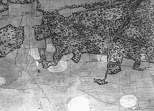
The first topographic map created by the Survey was originally a single, long and narrow sheet, about two feet wide and over nine feet long. Click image for larger view.
The U.S. Coast Survey created its first topographic map in 1834. At a scale of 1:10,000 (or about 6.3 inches to one mile), the map covered the shore of Great South Bay on Long Island, New York, between the towns of Babylon and Patchogue.
Coast Survey topographic maps eventually became known as topographic sheets, or “T-sheets.”
Plane Table Surveying
The first hundred years of shoreline mapping in the Coast Survey relied on a method called plane table surveying. The plane table was the best instrument for quick yet accurate topographic mapping.
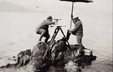
Rudimentary plane table methods had been used in Europe since the early 17th century, but more advanced techniques and equipment for plane table mapping were first introduced to the United States by Ferdinand Hassler. Here, a plane table is used to map an area in Alaska. Click image for larger view.
The first plane table crew of the Coast Survey drew its first shoreline map in New York in the fall of 1834. The next year, a second mapping party was formed. The number of parties grew as would their progress in mapping the coast. By 1855, 540 topographic survey maps, scattered throughout the Atlantic, Gulf, and Pacific coasts, had been completed and registered.
The plane table continued as the primary method of mapping the coastline for the next 80 years.
A Bird’s Eye View: Aerial Photography
By the late 1800s, photography was recognized as a useful tool for mapping. The U.S. Coast and Geodetic Survey (C&GS) first used a surveying camera with a plane table for mapping the international boundary between Alaska and Canada in 1894. This use of ground photos for mapping continued through the early 20th century.
By the turn of the century, aerial cameras with multiple lenses, and thus a much wider field of view, were developed in Europe. When these cameras were used with airships (dirigible balloons), photographs could be taken over pre-planned locations to cover a broad area. Once the airplane was invented in the early 1900s, aerial photography had a new and ideal platform.
The First Aerial Photo Projects
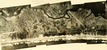
The first C&GS aerial photographic mission took place along the New Jersey coast, near Atlantic City, in 1919. This photo mosaic, which shows part of the project area, was prepared using images collected during the mission. Click image for larger view.
During World War I, the airplane proved to be useful for both combat and photo reconnaissance. It was shortly after the end of the War that C&GS became interested in using the airplane for mapping.
In 1919, C&GS started work with the U.S. Army Air Service to investigate using aerial photographs to compile coastal topography. The Air Service provided the aircraft, pilots, cameras, photographers, and developing services. The first project covered the area around Atlantic City, New Jersey. Many photographs, on both glass plates and roll film, were taken using two different cameras. Overall, this first photographic mission was considered a resounding success.
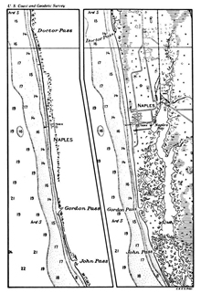
This image shows a chart of the same coast before and after an air photo resurvey. It had become possible, by air photo methods, to obtain the topography shown on the right at no greater cost than the limited ground survey on the left. Click image for larger view.
In 1920, the whole outer coastline of New Jersey was photographed and the photos were used to revise New Jersey coastal charts. Topography from aerial photographs was accurate enough to revise coastal charts for about one-third the cost of plane table methods and could be used to map areas where use of a plane table was problematic.
In 1921-1922, C&GS conducted a major aerial photo survey of the Mississippi River delta. The plan was to create original topographic maps—not just revisions—from the photographs. The success of the project proved that aerial photo mapping could replace the plane table, depicting more detail at lower cost. Topographic sheets covering the delta were completed in 1924.
Additional aerial photo surveys were flown in Florida (1926-1928) for chart revision, and the success of these projects led C&GS to expand a program for topographic mapping through aerial photogrammetry (the science and art of making accurate measurements from photographs). To support this program, the Photogrammetry Unit, under the Division of Hydrography and Topography, was established. This Unit eventually evolved into today’s Remote Sensing Division of NOAA’s National Geodetic Survey.
Nine Eyes are Better than One: Multi-Lens Cameras
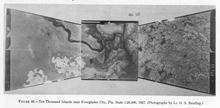
Photos taken with multi-lens cameras offer a larger view of the ground than those taken with a single-lens camera. This composite image was created using three separate photos all taken at the same time using a three-lens camera. Click image for larger view.
Early air photo projects used single-lens cameras. These cameras were simple to operate and produced good pictures, but they had very narrow fields of view that required many photographs to cover a moderately sized area. Photos taken at a higher altitude covered more ground area in each image, but at reduced detail.
The solution to this problem was to use cameras with multiple lenses. A multi-lens camera could take several photos looking down toward the ground at different angles. Since the multiple photos were all taken at the same time from a single camera, they could be combined into a single composite image that covered a much larger area of ground, effectively increasing the camera’s field of view.
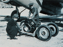
The C&GS nine-lens camera was enormous: fully equipped it weighed 750 pounds and the roll film it used was 200 feet long and 23 inches wide. It required a special hoist for loading into the airplane and its own cart for handling and transport.
Early on, the C&GS used the multi-lens cameras of the U.S. Army and Navy. Projects were flown using three-, four-, and even five-lens cameras. However, C&GS soon realized that the available cameras were not accurate enough to support the high precision required for topographic mapping.
In 1934, C&GS completed designs for a precision nine-lens mapping camera. The camera was built in 1935, although it would take several more months of calibration and adjustment before it was ready for mapping.
For the next 25 years, the C&GS nine-lens camera provided extensive aerial photo survey capability. It was truly a unique instrument (the only one ever built) that paid for itself many times over by reducing the need for expensive ground control operations associated with traditional topographic mapping. It was only taken out of service for two years to be rebuilt, following a deadly crash in Alaska in July, 1943.
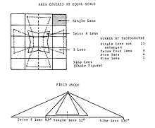
This diagram illustrates the much greater area covered by a single photograph from the nine-lens camera, compared to the area covered by photos from other single-lens and multi-lens cameras available in 1935. Click image for larger view.
The nine-lens camera was used for the last time in 1961, after having taken 141,000 photographs in all of the coastal states and several island territories.
Color and Infra-red Aerial Photography
During the 1950s, aerial cameras capable of taking color photographs were introduced. Color photographs were more natural looking than black and white photos, which made the identification and interpretation of various features in the image much easier.
With the appropriate filters, color photography could also show underwater features more clearly, making it possible to identify and map submerged rocks, reefs, and shallow areas. Measuring depths and mapping underwater features from aerial photographs is called photobathymetry. In 1958, the Coast Survey conducted a test project in Puerto Rico and obtained the first successful color aerial photography for photobathymetry.
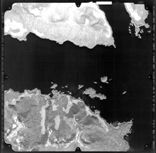
In a black and white infra-red photograph, land appears very bright and water appears black. Click image for larger view.
These new cameras were also able to use film that was sensitive to near infra-red (IR) light. Near IR light reflects strongly from vegetation and dry ground, but is almost totally absorbed by water. Black and white IR photographs show a sharp contrast between land and water, making it easier to accurately identify and map the shoreline in the photograph.
The line on the ground separating the land from the water (i.e., the shoreline) moves with the tide. Nautical charts depict the shoreline during mean high water (MHW), which is the average height of all high tides measured over many years. In order to accurately map the MHW line from IR photography, photos had to be taken during high tide. The first tide-coordinated IR photography for coastal mapping was obtained over Cobscook Bay, Maine in 1956.
At the time, commercial services for processing color aerial film were not available, so the C&GS built the first film laboratory for processing color aerial photography in the world. It soon became standard practice in C&GS to use both natural color and tide-coordinated IR photography.
We're Really Flying Now: C&GS-Operated Planes
The earliest aerial photo projects for C&GS were flown using U.S. Army and Navy Air Services aircraft and flight crew. Starting in 1940, C&GS used a U.S. Coast Guard airplane and crew for all coastal mapping aerial surveys, allowing C&GS to avoid the expense of purchasing and maintaining its own aircraft.
By the early 1950s, the need was increasing for more photography to support the growing coastal mapping program. C&GS began to lease private aircraft to fly aerial mapping missions. In 1964, after 25 years of working together, C&GS and the Coast Guard ended their arrangement for aircraft services. For the next few years, C&GS used leased airplanes for all aerial photo missions.
The First C&GS Plane
In 1965, the Coast and Geodetic Survey was reorganized, along with the Weather Service and some other agencies, to form the Environmental Sciences Services Administration (ESSA) in the Department of Commerce. Under ESSA, C&GS acquired a surplus deHavilland Buffalo airplane. The Buffalo was converted for aerial photography and went into service in 1969. This was the first aircraft owned and operated by C&GS, and served for 10 years before being retired.
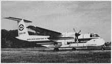
The first aircraft owned and operated by the C&GS Photogrammetry Division possessed all of the requirements needed in a photographic airplane. Click image for larger view.
In 1970, ESSA was again reorganized, and became the National Oceanic and Atmospheric Administration (NOAA).
A Growing Aircraft Fleet
In 1974, C&GS purchased its second aircraft, a Rockwell Turbo Commander. This new airplane replaced an Aero Commander that had been leased for the previous 18 years.
The Office of Aircraft Operations was created in 1983 to consolidate all of NOAA’s aviation assets. Though the Turbo Commander continued to support the coastal mapping program, by the mid-1980s, the Photogrammetry Division had access to several aircraft that could support a variety of photographic missions.
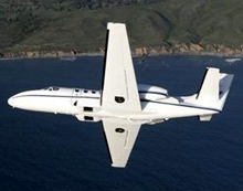
In this image of the NOAA Citation II jet, the dual camera ports can be seen on the bottom of the fuselage just in front of the wings. For 20 years, this aircraft was the workhorse of the Coastal Mapping Program and has supported many other scientific projects throughout NOAA.
In 1984, NOAA began leasing a used Cessna Citation II jet aircraft for coastal mapping. The Citation jet could operate at high altitude (up to 43,000 feet) and with a long operational range. Also, its high speed allowed it to move quickly from one area to another, taking advantage of favorable weather conditions in different parts of the coast.
The Citation was modified to contain dual camera ports in the bottom of the fuselage, so that two cameras could be used simultaneously. Usually, one camera was loaded with color film, and the other with IR film. Soon, almost all the coastal mapping projects were flown on the jet. In 1988, NOAA purchased the Citation, adding it to the agency’s fleet of aircraft.
Conclusion
Since the creation of that first “T-sheet” over 170 years ago, the tools and technologies used to map our nation’s coasts have changed. However, NOAA and its predecessor organizations have continued to produce maps of the coastal regions of the United States and provide data for nautical charts needed by mariners to safely navigate our waters.
In addition, since the late 1930s, aerial photographs that are the source for shoreline information on nautical charts have also provided information to define the boundaries between private, state, and federal ownership and jurisdiction, and to make coastal management decisions, plan waterfront development, and locate features or obstructions to marine and air navigation.
Contributed by Tim Blackford, NOAA’s National Ocean Service
