
 Great Theodolite
 The Bache- Wurdemann Compensating Device
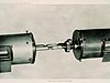 Eimbeck Duplex Bars
 Iced Bar B 17
 Steel Tape with Tape Stretcher
 Invar Tape
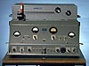 AGA Geodimeter NASM-2A
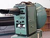 Tellurometer Model M/RA 1
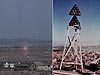 Laser Signal and Prismatic Mirror Reflecting System
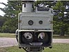 AGA Geodimeters, Models 4D and 4L
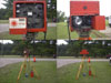 Big Red
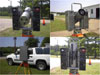 AGA Geodimeter Model 6
 Hewlett-Packard Model 3800B Distance Meter
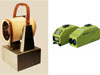 Tellurometer Model MA-100
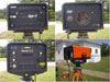 Ranger III and Rangemaster III
 Topcon ET-1 Total Station
 Trimble GPS Antenna
AGA Geodimeters, Models 4D and 4L
This photograph shows AGA Geodimeters Models 4D (top) and 4L (bottom). These instruments worked by sending a light signal of known wavelength to a reflector. The wavelength of the returning signal was compared to the outgoing one, and the difference (called the "phase shift") was measured. Using multiple frequences of light, the instrument computed a distance based on the known lengths and measured phase shifts of returning light waves.
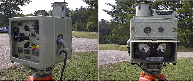
The control panel and optics of a Model 4D Geodimeter. Photos courtesy of Charlie Glover.
The control panel and optics of a Model 4L. Photos courtesy of Charlie Glover.
Geodimeters, first developed in the 1950s, evolved quickly in the 1960s. In the "4 series" (shown in the photo), weight was scaled down to 20 pounds and measuring time was reduced from 45 minutes to 10 minutes, compared to earlier Geodimeter models.
For lightwave instruments, a complete set of measurements consisted of four separate observations: two measurements with the prism over true center, then measurements with offsets of 0.4 meters. Two complete sets of these measurements, separated by 24 hours, were made. Accuracy of the measurements could be affected by optics alignment, frequency drift, and calibration curve errors in the phase readings. Wet and dry bulb thermometer readings were taken at one end of the line and temperature and pressure readings were taken at both ends of the line both before and after measurements. Altimeter readings were also taken.
The 4D used a high-pressure mercury vapor lamp rather than a common tungsten light bulb as its light source. First manufactured in 1963, the "D" in its designation indicated that it could be used in daylight. The Coast and Geodetic Survey (C&GS) used this model throughout the 1960s.
In 1966, the 4D was modified to use a laser as its light source, in order to increase its range in moderate haze and to measure longer distances in bright sunlight. C&GS technician George Lesley replaced the mercury vapor lamp with a three-milliwatt helium-neon gas laser. The modified 4D was designated "4L," and replaced the 2A and 4D models on the Transcontinental Traverse. Later, the three-milliwatt laser was replaced with a six-milliwatt laser and the model was renamed "4L 6A."
As a result of the technology developed by C&GS, AGA produced the first commercially available electronic distance measurement instrument with a laser light source, which it designated Model 8. These models were also used in Transcontinental Traverse observations.
- Distance Measurement Instrument Shown: AGA Geodimeters, Models 4D and 4L
- Location: Corbin, Virginia
- Manufacture Date: 1960s
- Dates of Use: 1960s - 1970s
- Photo Date: 2006
Works Consulted
Burger, T. C., Tomlinson, R. W. (1975). Electronic Distance Measuring Instruments. Washington, D. C.: American Congress on Surveying and Mapping.
Meade, B. K. (1967). Progress and Results of High-Precision Traverse Surveys. Presented to the Joint American Society of Photogrammetry-American Congress on Surveying and Mapping Convention, March 5-10, 1967.
Smith, J. R. (1983). Geodimeter 1947-1983. Unpublished.