Survey Towers: Raising the Level of the Survey
This collection of photos and drawings of 10 survey towers traces the evolution of the towers used by Coast and Geodetic Survey surveyors from the mid-1800s through the 1970s to obtain the clear lines-of-sight needed to conduct the surveys that are the backbone of our nation's spatial reference framework.

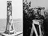
One of the earliest sketches of first Coast Survey Superintendent Ferdinand Hassler's work, from 1837, shows a tent, the observing stand holding the instrument, and the separate footboards to support the observer.
Every photographer and every surveyor knows that you do not want to disturb your tripod during precise work. Just walking around a survey instrument can disturb the instrument sufficiently to degrade the observations.
To minimize any disturbance of the survey equipment by the observer's movement, U.S. Coast and Geodetic Survey (C&GS) surveyors built foot-boards around wooden stands holding surveying instruments. These foot-boards were supported by wooden stakes completely separate from the stakes holding the observing stand in place.
This idea of independent support carried on through the years. Surveyors needed a clear line-of-sight between survey marks in order to measure angles and distances. In hilly terrain, marks were placed on the highest point available in order to help ensure a clear line-of-sight to other marked high points in the area. Towers were only needed when the hilltops were covered with trees. In flat terrain, towers were almost always needed to see over the trees along the path to the adjacent survey marks. Even in flat, tree-less terrain, towers were needed just to compensate for the Earth's curvature and refraction. For example, on a 20-mile-long survey line, a 58-foot tower would be required at each end to allow for the Earth's curvature. If a tower was only present at one end of the survey line, this tower would need to be 230 feet high to create the necessary clearance along the line.
These towers were important tools in the surveying work of the C&GS.
About this Collection
This collection of 10 survey towers traces the evolution of towers used by C&GS surveyors, from wooden towers that were constructed by survey parties and could only be used once to steel towers that could be assembled, used for the survey, disassembled, and transported from location to location via truck. Used by the C&GS from the mid-1800s through the 1970s, these towers allowed surveyors to obtain needed clear lines-of-sight—by raising a signal for observers to sight on from a distance, raising the observer himself, or both.
The towers represent important tools in surveying our nation and reflect the determination of surveyors dedicated to getting the job done…no tree or mountain was enough to stop these men from completing the surveys that today are the backbone of our nation's spatial reference framework, called the National Spatial Reference System (NSRS).
You can browse through the towers in the collection by clicking on the links to the right, or click here to view the items in the Survey Towers Collection.
A History of Survey Towers

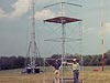
The towers used by Blunt included an inner tower for supporting the survey instrument and an outer tower for independent support of personnel. Thus, the twin towers were a continuation of the original idea of independent support for instruments.

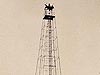
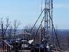
A Bilby Tower adorned with an observing tent to protect the inner tower, where the survey instrument sat, from the wind.
One of the earliest mentions of survey towers is in an 1844-report of a Chesapeake Bay survey by Edmund Blunt of the C&GS. Since land on the east side of Chesapeake Bay is very flat, Blunt built towers ranging from 30- to 45-feet high in order to conduct his surveys.
In 1859, the Epping Baseline in New England was connected to a growing national survey network using 40-foot towers. Strong winds led C&GS Assistant Charles Boutelle to drape light canvas on the outer tower, to protect the inner, instrument tower from the wind.This method was successful and constructing observing tents became standard procedure.
Tower Materials
Over the years, survey towers have taken on many forms. Early wooden towers had four sides, while later towers had only three sides, forming a classic triangle. Some types of towers were built with local timber, taking advantage of available materials at or near a survey site. Other towers were more standardized in an attempt to save time and money. Towers have been constructed of raw timber, standard-sized lumber, steel (pipe and angle-iron), and aluminum. Some towers were supported by guy wires, others were self-supporting. The C&GS used mainly wooden towers until the advent of steel Bilby towers in 1927. An exception to this was the use of steel gas-pipes for hydrographic signal tripods, which were used as early as 1853. Wooden towers were still being designed as late as 1934, and at least one short wooden tower was used as late as 1980 in Texas.
Tower Heights
Tower heights have varied from a few feet (for ground observations) to 275 feet! Towers thus raised the level of the survey line-of-sight. The twin tower concept (one tower inside of another) raised the level of survey quality by isolating the vibrations caused by the movement of the people from the tower supporting the delicate survey instruments.
The required height for a tower was usually determined in advance by a reconnaissance survey party. This type of small party used maps and survey instruments to measure the heights of trees and the heights of the land along the line-of-sight between existing and proposed survey mark locations. The reconnaissance party had a complex task because they also had to consider the geometry of the triangles they were planning, the curvature of the Earth, and atmospheric refraction. Ideally, in triangulation, all measured triangles should be equilateral (equal sides and equal angles). However, this was usually not possible due to varying terrains.

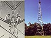
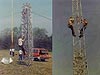
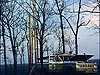
The inner tower in this photo had an observing height of 120 feet and the outer tower's signal height was 275 feet.

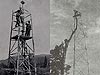
Jasper Bilby—the inventor of the Bilby Tower—atop a guyed pole doing reconnaissance in 1903. Note his horse and buggy.
Because of the heights involved, building towers and observing from towers was dangerous. The Survey had an excellent safety record over the many years towers were used. The standard joke was that the first time a person climbed a steel tower, he left his fingerprints in the steel on the way up!
Contributed by Commander George E. Leigh, NOAA Corps, (Ret'd.)
Works Consulted
Bilby, J.S. (1929). Bilby steel tower for triangulation. USC&GS Special Publication No. 158.
Bilby, J.S. (1940). Bilby steel tower for triangulation. USC&GS Special Publication No. 158, Revised Edition.
Bilby, J.S. (1943). Signal building. USC&GS Special Publication No. 234.
Richards, J.K. (1965). Bilby steel tower for triangulation. USC&GS Publication 62-3.
Woodford, A.M. (1991). Charting the inland seas: A history of the U.S. Lake Survey. U.S. Army Corps of Engineers.