
 Thomas Jefferson's Theodolite
 Hassler's Camp
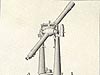 The Great Theodolite
 Würdemann Six-inch Theodolite
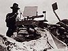 Heliotrope
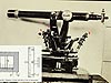 Micrometer Scale
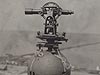 Theodolite Mounted on Water Tank
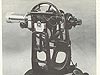 Seven-inch Repeating Theodolite
 C&GS Twelve-inch Theodolite
 Wild T-4
 K&E Theodolite, Parkhurst Design
 Wild T-2
 Wild T-3
 Topcon GPT-3002LW Total Station
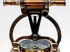
Micrometer Scale
The diagram in the left inset illustrates the scale that an observer using a theodolite would see when looking through a micrometer. Read through a microscope, a micrometer allowed the accurate subdivision of angles as the theodolite was turned. This accuracy was required to achieve higher-order surveys.
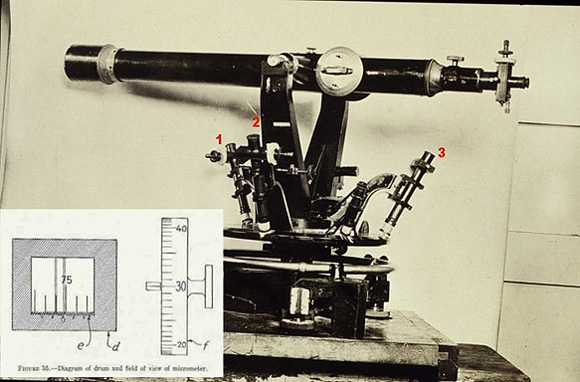
Diagram showing a 12-inch theodolite with three microscopes indicated. These microscopes were used to read the micrometer scale and drum illustrated in the lower left inset.
This image shows a theodolite micrometer and the microscopes used to read them. A micrometer allowed theodolite users to accurately subdivide angles as the instrument was turned on its circle. Micrometers were first used combined with a telescope in 1690 and used by astronomers to measure the diameters of heavenly bodies. The wires shown in the field of view on the left side of the image would occasionally break, so older Coast and Geodetic Survey (C&GS) triangulation manuals required that all field parties carry a spider's cocoon with them and included instructions for replacing broken micrometer wires with threads from the cocoon.
Historical Reference
As the ability to accurately scribe angles on the circle of a theodolite evolved, so did the ability to read the angles. Verniers directly read by magnifying glasses were replaced by micrometer microscopes having wires that subdivided the theodolite circle more finely. The most accurate surveys, called first-order surveys, could only be performed using theodolites which could be read to less than one second of arc. In order to compensate for any error in the instruments, multiple readings were taken from different parts of the circle; first forward, then with the telescope reversed, or "plunged." Sixteen forward plus sixteen reverse angles were required for one first-order observation. Requirements for how much error was allowed when the final computations were done were also well defined: ±0.8 inches (2.0 centimeters) should be the average and ±2.5 inches (6.5 centimeters) was the maximum error allowed. Requirements for second- and third-order observations were equally well defined, but with slightly larger tolerances.
- Instrument Shown: 12-inch theodolite, micrometer scale and drum
- Location: Unknown, but probably taken at the C&GS office in Washington, DC
- Manufacture Date: Unknown
- Dates of Use: Unknown
- Photo date: Theodolite: 1916, Micrometer inset: Unknown
Works Consulted
Federal Geodetic Control Committee. (1980). Specifications to Support Classification, Standards of Accuracy, and General Specifications of Geodetic Control Surveys. Rockville, MD: National Ocean Survey.
Hodgson, C. V., (1943). Manual of First-Order Triangulation. C&GS Special Publication No. 120. Washington, DC: GPO, p. 42-43.
Wallis,
D. A. (2005). History of Angle Measurement. Retrieved June 28,
2006, from: http://www.fig.net/pub/cairo/papers/wshs_01/wshs01_02_wallis.pdf