Signals: Flags, Banners, Cones, and Lights Help Direct Surveys
Since the early 1800s, the National Geodetic Survey and its predecessor organizations have been working to establish a consistent and accurate framework from which to conduct land and coastal surveys in the United States. An integral part of completing these surveys was the measurement of angles, through a process known as triangulation. Signals—used to help surveyors sight on distant survey marks—were integral to obtaining high-quality angles.
Did you know that activities such as transportation, navigation, communication, delineation of property boundaries, mapping and charting efforts, defense operations, and many others all rely on a consistently and accurately defined network of survey points? For nearly 200 years, NOAA's National Geodetic Survey (NGS) has defined and managed this network, known as the National Spatial Reference System (NSRS).
Here, we'll take a look at the evolution of one of the crucial tools used by early surveyors to establish the NSRS: signals.
Some Information about Signals
Most of the survey work accomplished to establish the nation's survey network by the U.S. Coast and Geodetic Survey was done by observing the angles of triangles. This process, known as triangulation, involved observing the angles of thousands of triangles, all across the U.S. All angles were measured multiple times to help detect errors.
While excellent instruments were available to measure the angles, the key to high-quality angles was to have the angle measuring instrument centered over the survey point, and to have some sort of signal or target centered over the distant survey marks. This signal gave the observer looking through the telescope of the instrument something to sight upon.
Ferdinand Hassler, the Survey's first superintendent, had used spheres covered in white cloth as signals in his native Switzerland. However, on the U.S. East Coast, with its high humidity and much poorer visibility, this type of signal did not work well. Thus, surveyors had to take a different approach.
During the early days of the Survey, several types of signals were used. These signals included wooden poles or towers topped by tin reflectors, flags, one or two cloth cross-banners, or wooden targets. Also, systems of mirrors, called heliotropes, were used to reflect sunlight once or twice, depending on the position of the sun, along the line-of-sight to distant survey stations.
In the 1870s the C&GS experimented with the light beam from lamps burning whale oil, kerosene, and magnesium, none of which worked well for long survey lines. Acetylene lamps were introduced in the late 1890s. Around 1900, bicycle acetylene lamps were used by the C&GS for the survey along the 98th meridian and were found useful for surveying distances up to about 34 miles. Larger acetylene automobile headlights were also eventually used successfully. Two of these automobile lamps stacked one above the other were observed at a distance of 133.9 miles at Pilot Peak, Nevada.
The development of the electric automobile headlight resulted in an excellent signal lamp. A bulb with a special filament was made at the request of the C&GS. In 1920, the light from two of these headlights was visible at a distance of 152.9 miles to an unaided eye (no telescope). By the mid-1920s, the electric signal lamp was the standard. Over the years, electric lights were made smaller and smaller, as more efficient bulbs and reflectors were produced.
After the development of electronic distance measurement instruments, special prisms (mirrors) were used to reflect a light signal from a distant survey mark back to the observer. These prisms also needed to be mounted so that they were centered directly over the distant survey mark.
Soon after NGS began performing surveys using Global Positioning System (GPS) technology in 1983, angle observations and the need for visual signals ended. The signals described above allowed accurate triangulation methods to be used to survey the nation. GPS now enables surveyors to determine positions faster, cheaper, and more accurately.
The images below include a variety of the signals used throughout the history of the Survey, with a brief explanation on the usage of each.


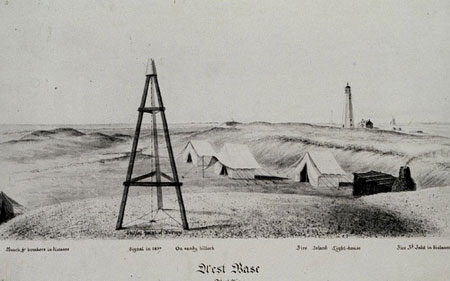 Tin Cone on Tripod: This type of signal was used in the early 1800s. The tripod was carefully centered over the survey mark and a shiny,
tin cone was suspended from the top. On a clear day, the sun would reflect off the tin cone and might be visible at the observing station several miles away.
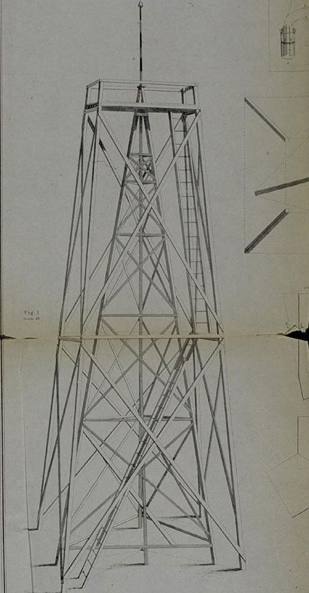 Blunt Tower
with Signal: This type of tower with signal was used on a survey off the eastern shore of Chesapeake Bay in 1844. The signal is a tin cone that sits on top of the
tower. The angle observer would stand on the outer tower.
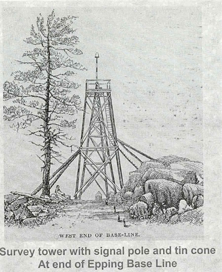 Epping Base Line Signal: The signal atop the tower in this image, taken in 1857, was used as a sight for connecting the base line to the main
scheme triangulation. Observing would take place from the platform atop the outer tower.
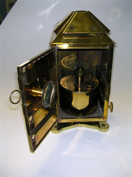 Oil Lamp: This actual brass oil lamp was used by the Survey in the late 1800s. In this photograph, the back is open showing the lamp and small
reflector. The front of the lamp has a narrow adjustable slit to control the amount of light exiting the lamp. The lamp is now part of the National Geodetic
Survey historic collection.
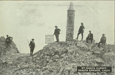 Mt. Shasta Signal: This signal was constructed by C&GS in October 1875 to enable accurate observations to be observed on
Mt. Shasta, California, without necessitating sending surveyors to the top of the mountain on every occasion. The signal was almost 15 feet tall and was carried to
the top of the 14,100-foot mountain in sections and then bolted and riveted together. The top conoid-shaped section was designed to reflect sunlight early and late
in the day to distant observers. This top section was about three feet tall and was made of copper, plated in nickel and burnished to increase reflectivity. The
signal was knocked off the top of the mountain in 1903, apparently by lightning. The top section is presently on display in the Sissons Museum in Mt. Shasta. The
longest survey line ever observed was between Mt. Shasta and Mt. Helene, 192 miles to the south. However, the line was observed in both directions using heliotropes
as the signals rather than this metal reflector signal because of the great distance.
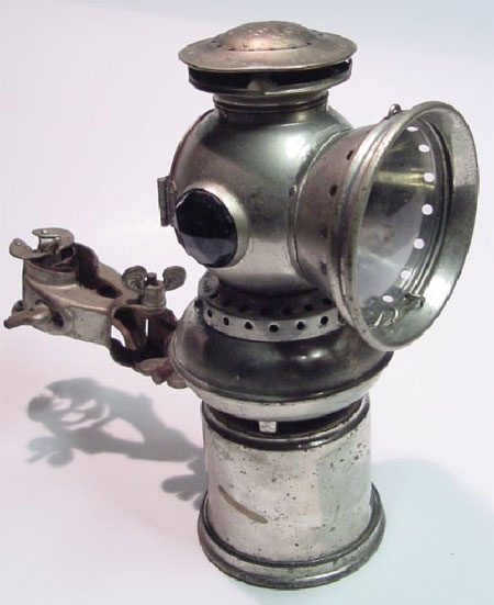 Bicycle Acetylene Lamp: This signal, an acetylene lamp is similar to the type used by the Survey for night observations
beginning about 1900. These lamps were much brighter than magnesium lamps and were useful up to about 30 miles. Image courtesy of Steve Johnson.
 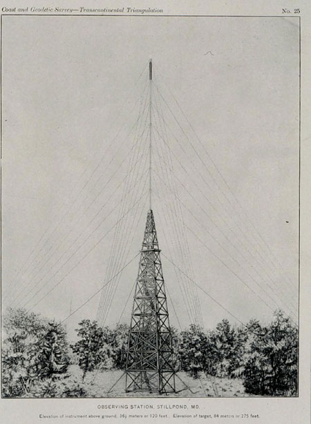 275-foot Signal: This tall signal was constructed of wood. The drawing shows that the signal sat atop the inner tower and was steadied using
rope. Observations could be made from the outer tower at a height of 120 feet, but not from the very top of the structure.
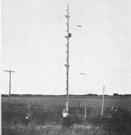 Signal Mast of 1917: This wooden mast was used to elevate a light directly over a survey mark in 1917.
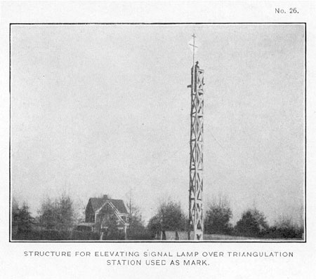 Signal Tower of 1917: This wooden tower was used to elevate a light directly over a survey mark in 1917.
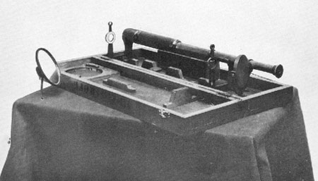 Heliotrope: This heliotrope from 1914 was an instrument which could reflect the sun's rays once or twice, if needed, so that the
light beam would travel directly along the line-of-sight to a distant survey mark where an observer was turning angles. The telescope allowed the operator to
sight on the distant survey mark and ensure that the heliotrope was aimed correctly.
 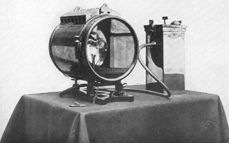 Acetylene Lamp: This signal, an acetylene lamp from 1914, was used by the C&GS to show a light for evening observations. The lens would focus the light
in a narrow beam that could be aimed along the line-of-sight. This model was larger than the earlier bicycle acetylene lamp and useful for covering greater distances.
On an extremely clear night, these lamps were visible to the unaided eye at 100 miles. Acetylene lamps mounted behind a pair of powerful condensing lenses were used for
night signals beginning in the year 1900.
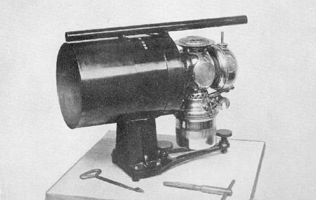 Acetylene Lamp: This signal, an acetylene lamp from 1917, showed a light for evening observations. The lens would focus the light in to a
narrow beam that could be aimed along the line-of-sight. This model had a sighting tube on top to assist the light-keeper in pointing the light correctly toward
the distant station.
 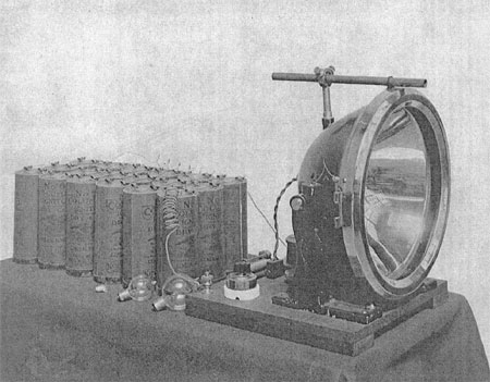 Large Electronic Signal Lamp: This lamp was an automobile headlight with a 23-centimeter parabolic reflector. It was
adapted to survey use by the C&GS and first used in the field in early 1916. The photo shows the lamp with an aiming device mounted on a board, a battery bank, and spare bulbs. Special bulbs with
concentrated filaments were designed and produced at the request of the C&GS. These bulbs allowed lamps to produce narrow, intense beams of light. The bulb's
maximum intensity was at 9.5 volts and 2.4 amps of current. In 1920, the electric light was used successfully over a line 153 miles long. A smaller, less bright
version of this lamp requiring less power was also used.
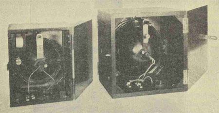 Electric Lamps: These electric lights were the standard signals used for triangulation in the mid-1920s. This photograph shows the rear
view of both sizes of lights. The wiring, the rear of the reflectors, and the silver-colored aiming device can be seen. The smaller light on the left was useful for
survey lines up to about 25 miles in length. Both lights shown here were powered by batteries. Care was needed to focus the light into a narrow beam and to align the
pointing device with the light beam. These newer models were built inside a rectangular box so that the lights could be stacked one upon another for showing lights in
several directions simultaneously.
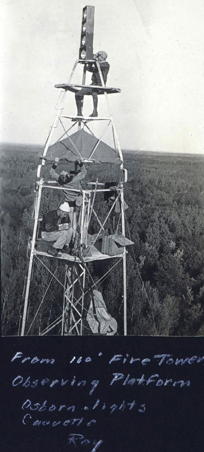 Bilby Tower
with Four Lights: The portable and re-usable steel Bilby Tower was developed in 1926-1927 and first used in 1927 to raise surveying equipment to a sufficient height
to clear obstructions and provide the necessary clear line-of-sight between adjacent survey marks. This photo shows four signal lights mounted on the top of the outer
tower of the Bilby Tower. The lights were used by four other angle observers turning angles from their own towers. The instrument for observing angles from this tower would be mounted
atop the tower, next to the man adjusting the overhead canvas. The reflector for these large, wood-framed lights was seven inches across.
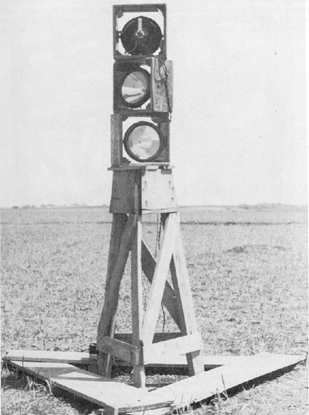 Four-foot Stand with Three Lights: The four-foot stand in this image held three signal lights which were directed
toward distant observers in three different directions.
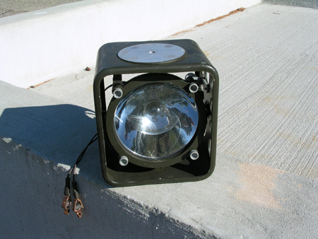 Grid Light: These steel-framed lights, called "grid lights," were smaller than earlier, wood-framed lights. They had
large bulbs and large reflectors for use on long survey lines.
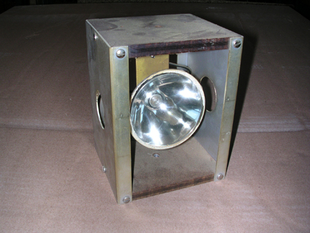 "PeeWee" Light: This smaller signal light was called the "PeeWee" light since it was much smaller than previous wooden and metal models. The
PeeWee light reflector was only three inches across. This light had several variations of material and accessories. PeeWee lights were made of wood, metal, and
casting resion. Some models included a level bubble and some came with a rheostat to control light intensity. The PeeWee was in use in the mid-1950s and continued
to be used until the advent of the Global Positioning System in the early 1980s.
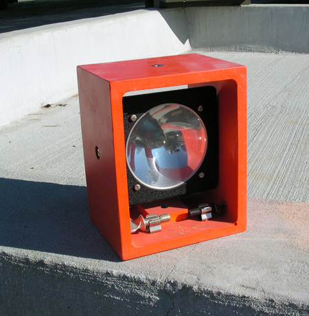 Resin "PeeWee" Light: This orange resin "PeeWee" light was the last variation of this signal made. It was designed and made by NGS personnel at the
NGS Instrument and Methodology Branch at Corbin, Virginia, in approximately 1980. This model had a rheostat, electric connections, an aiming sight, and holders for two
spare bulbs.
Works Consulted
Bowie, W. (1922). Geodetic Operations in the United States January 1, 1912 to December 31, 1921. Special Publication No. 81, USC&GS.
Bowie, W. (1926). Long lines of triangulation. Geographical Review, 16 (4): 638-641.
Hodgson, C.V. (1921). Utah-Washington Arc of Precise Triangulation. Special Publication No. 74, USC&GS.
Hodgson, C.V. (1926). Manual of First-Order Triangulation. Special Publication No. 120, USC&GS.
U.S. Coast and Geodetic Survey. (1880). Annual Report of the USC&GS for 1880, Appendix No. 8 "Report on Geodesic Night Signals."
U.S. Coast and Geodetic Survey. (1921). Annual Report of the USC&GS for 1921, pp109-110.
