Bilby Tower Ingenuous Features
With parts bearing interesting names and nicknames such as spaghetti, wishbones, glass leg or window leg, A-board, follies, and knob legs, Bilby Towers had many ingenuous design features that contributed to the popularity and endurance of these towers.
Self-Supporting
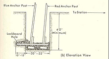
When a tower needed to be built on top of bedrock, the mudsills would be held in place with sand bags and the tower might be guyed. Click image for larger view.
Bilby Towers were self-supporting, usually built with no guy wires. Guy wires were known to introduce vibrations in even moderate winds, which would degrade the survey observations. Each tower leg was fastened to a wooden mudsill, between 3.5 and 4 feet in length, at the bottom of a five-foot-deep hole. After installing lock-boards across the mud sills and into cut-outs in the side of the hole, the holes were then filled with dirt. This foundation system provided great strength.
The steel anchor posts had holes one-inch apart to allow the builders to level between the legs and select the correct hole to start the construction. This ensured that the tower would be level.
Color-Coded Parts
All the parts of the tower were held together with steel nuts and bolts, and each steel part was color-coded. The inner tower parts were painted with a red band and the outer tower parts were painted with a blue band. Because of this color-coding, the inner tower was known as the “red” tower and outer tower called the “blue” tower. The color-coding helped to identify parts and speed tower construction.
Tower Extensions
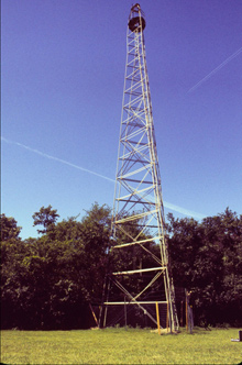
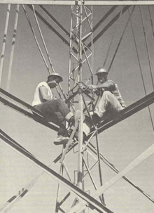
Ten-foot vertical extensions were nicknamed “supers,” for superstructure. The regular shape of the outer tower was a gradual inward slope, but the “supers” were vertical. When climbing the tower, the climber sometimes felt like the “super” was sloping backwards! These images show a Bilby Tower with one super inserted and a tower with two supers. Note that each super had two horizontal “ties” so that one super appeared to have two sections.
Occasionally, a tower was not tall enough to clear all obstructions as originally built. In this case, one or more 10-foot vertical extension sections, or “supers,” could be added just below the observer’s cage. Jasper Bilby stated that as many as four or five of these sections could be added, and he recommended the use of guy wires if this was the case. In practice, usually no more than three “supers” were used in order to maintain the required stability.
Simultaneous Observations
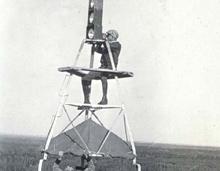
The top of the outer tower was officially called the “trianglehead,” with its “lightplate” on top. Click image for larger full view and full caption.
Bilby Towers were designed so that observations could simultaneously be made from the tower itself and toward the tower from observers standing on other towers. That is, an observer could be working on the observation platform while showing signal light(s) 10-feet over his head from the top of the outer structure. Observers on other towers could then sight on the signal light.
The Swivel
Since the tower extended above the height of the survey instrument, there was the possibility that one of the tower legs would block the line-of-sight to another survey mark. This possible circumstance was solved by the tower design. At the same height as the instrument, a special “U” shaped piece was inserted in each tower leg. This U-shaped piece was officially named the “swivel,” but was nicknamed the “window” or “glass.”

The “U” was mounted on its side with in-line bolts inserted through the top of each side of the “U.” Click image for larger view.
If one of the legs was on-line to another survey mark, the observer gave the “window” a hard kick, rotating it around the axis of the bolts and moving the bottom of the “U” off the line-of-sight.
The Welded Section
The top portion of the inner tower was made of many small pieces of steel. Rather than having to assemble and dissemble this section each time a tower was built, this section was welded together at the factory and named the “welded section.”

In this photo, the narrow welded section is being bolted to the tower.
The top of this welded section was also adjustable up and down, so that the observer could set it at his correct height for comfortable survey observations. The adjustable section was held in place with special “V” shaped clamps.
Tower Legs
Each leg of a Bilby Tower was 13 feet, 9 inches long and was bolted to the legs above and below it and also to the diagonals and horizontal ties. The diagonals added rigidity to the tower. Up to the 37-foot section, the diagonals were angle iron (L-shaped), like the legs and ties. For the 37-foot section and the sections above, the diagonals were steel rods. Since the upper part of the tower did not need to be as strong as lower parts of the tower, the upper rods weighed less and were less susceptible to friction from wind.
Horizontal ties connected each leg to the other two legs, at the top and bottom of each 13-foot leg section and also at the mid-point. This meant that the builders could stand on one horizontal tie and reach up to bolt on the next tie. This and the modular nature of the tower design allowed the tower to be built without external cranes and in varying heights as needed.
Tower Heights
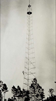
A photo of a Bilby Tower built in 1935. Note each “super” had two horizontal ties.
Standard tower heights were 24, 37, 50, 64, 77, 90, 103, and 116 feet. For a short time, 129-foot towers were also manufactured, but these were found to be too heavy for ease of construction and transport. The heights given are actually the heights of the inner, red tower (since this was the important height-of-instrument).
The outer, blue tower was actually 10 feet taller than the inner tower. If the reconnaissance called for a 90-foot Bilby Tower, it was known as a “90,” but the builders would actually not be done until they reached 100 feet of height. The most common sizes were 77 and 90 feet to clear typical tree heights.
A complete 90-foot tower weighed 5,270 pounds. The tallest Bilby Tower on record was 159 feet. It was a 129-foot tower, with 10 feet to the blue top and two 10-foot supers.
